EICR Checklist: What Electricians Should Check Before Issuing a Certificate
A full EICR checklist: visual inspection, dead testing, and live testing steps.

Written by
Michael Adrian
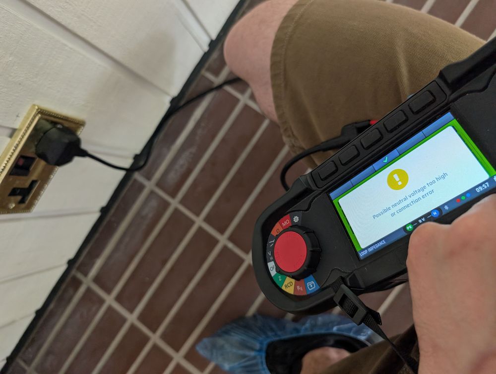
Bad earth connection fault
EICR Checklist: What Electricians Should Check Before Issuing a Certificate
An EICR is a structured condition report on an existing electrical installation, carried out against BS 7671. It's not a quick visual once-over — it's a documented sequence of visual inspection, dead testing, and live testing, recorded on a prescribed form and signed off by a competent person.
If you're the one signing the declaration, the quality of that report sits on you. Miss a test, misread a value, or tick a box you didn't actually check, and the report is wrong — regardless of how clean the install looks.
This checklist walks through the EICR in the order you actually carry it out: pre-inspection prep, visual inspection against the Schedule of Inspections, dead tests, live tests, and then the declaration and recommendations. It's aligned to the BS 7671:2018+A4:2026 model form, which is the current standard from 15 October 2026.
What Is an EICR and Who Can Issue One?
An Electrical Installation Condition Report (EICR) is a formal assessment of the condition of an existing electrical installation, carried out in accordance with BS 7671 Part 6. It records the scope of the inspection, the tests carried out, any observations, and an overall outcome — Satisfactory or Unsatisfactory.
EICRs are legally required for private rental properties in England at least every 5 years, or on change of tenancy, under the Electrical Safety Standards in the Private Rented Sector (England) Regulations 2020. Landlords face penalties for non-compliance. The Electricity at Work Regulations 1989 also places a duty on employers and self-employed electricians to maintain safe installations — EICRs are the standard way of demonstrating that.
Who can issue one? The inspector must be a competent person — someone with the knowledge, training, and experience to carry out the inspection and testing safely and accurately. From 1 October 2026, the bar gets more specific: every individual electrician carrying out EICRs under a certified business must hold a Level 3 qualification in inspection and testing (C&G 2391-52 or equivalent), have at least 2 years of documented experience, and show evidence of ongoing CPD. These requirements come from the updated EAS October 2024 and have practical regulatory effect through scheme membership.
If you're not sure whether you meet the competence bar, you shouldn't be signing EICRs. That's not gatekeeping — it's the legal reality.
Before You Arrive On Site: Pre-Inspection Preparation
Good EICRs start before you get to the property. Turning up unprepared is how things get missed.
Review the Previous EICR and Installation Records
If a previous EICR exists, read it. Note any C2 or C3 observations, FI codes, and recommendations — you need to check whether previously flagged issues have been resolved. If there's an Electrical Installation Certificate (EIC) or Minor Electrical Installation Works Certificate (MEIWC) on file, review those too.
The previous EICR tells you what to look at harder. If the last inspector flagged corroded bonding on the gas pipe, that's the first thing you check.
Confirm Scope, Access, and Limitations
Contact the client before the visit. Confirm:
- Which parts of the installation are covered (the whole property, common areas only, a specific circuit?)
- Any agreed limitations and the reasons for them (fitted kitchen units preventing access, areas in use, etc.)
- Access arrangements (keys, alarm codes, occupancy, isolation windows)
- Whether the supply can be isolated — dead testing requires disconnection
Limitations agreed in advance go in Section D of the EICR. Limitations discovered on site that weren't agreed in advance need to be recorded with reasons — and may affect the validity of the report.
Check Equipment and Test Instruments
Your test gear must be calibrated and in date. You need:
- Multifunction tester (MFT) with calibration certificate
- Insulation resistance tester (usually integrated into the MFT)
- Phase rotation tester (for three-phase installations)
- Tong tester / clamp meter for current measurement
- Approved voltage indicator (GS38 compliant) for safe isolation
- Lock-off kit and warning notices
If your MFT calibration is out of date, your test results are not valid. Don't start the job.
The EICR Form Structure (Appendix 6, BS 7671:2018+A4:2026)
The EICR form is defined in Appendix 6 of BS 7671. The A4:2026 version is the current model form. If you're still using A2 templates, you can transition until 15 October 2026 — after that, the previous edition is withdrawn.
The form is structured as follows:
| Section | Title | What You Record |
|---|---|---|
| A | Details of the person ordering the report | Client name, address, contact |
| B | Reason for producing the report | Periodic, change of tenancy, insurance, etc. |
| C | Details of the installation | Address, type, occupancy, age, last inspection |
| D | Extent and limitations of the inspection | What was inspected, what wasn't, and why |
| E | Summary of the condition of the installation | Satisfactory or Unsatisfactory, observations count |
| F | Recommendations | Remedial actions, further investigation |
| G | Declaration | Inspector signature, date, competence details |
| H | Schedules | Schedule of Inspections + Schedule of Test Results |
| I | (Where applicable) Additional information | — |
| J | (Where applicable) Particulars of signatures | — |
| K | Observations | Itemised list of defects with classification codes |
The two schedules are where the actual work gets recorded:
- Schedule of Inspections — a structured visual inspection checklist (items 1.0 through 8.0+), with each item ticked as satisfactory, unsatisfactory, or not applicable
- Schedule of Test Results — every circuit tested, with measured values for continuity, insulation resistance, polarity, Zs, Ipf, and RCD operation
The A4 form adds SPD type columns (T1, T2, T3) to the Schedule of Test Results and updates references to align with the revised Part 6. If you're using older software templates, check they've been updated.
You can download the official model forms from the IET website.
Visual Inspection: The Schedule of Inspections
Visual inspection is where good electricians separate themselves from box-tickers. This is where you find the things that explain your test results later — damaged accessories, overheating signs, DIY alterations, poor workmanship.
You're inspecting the installation, not testing it yet. But if you spot something dangerous during visual — exposed conductors, burnt breakers, water ingress — that's a C1 on the spot, and you follow the C1 procedure immediately.
Intake Equipment (Item 1.0)
Visually inspect the external condition of the distributor's equipment — service cable, service head, earthing arrangement, meter tails, metering equipment, and isolator if present. This equipment belongs to the DNO/supplier, but you still need to inspect it. If you find a defect, inform the person ordering the report immediately and follow up in writing. It's their responsibility to notify the DNO.
Check:
- Service cable condition (insulation, support, weathering)
- Service head integrity (no cracks, no signs of overload)
- Earthing arrangement (TN-S, TN-C-S, TT — confirm and record)
- Meter tails condition and sizing (minimum 25mm² for PME supplies)
- Metering equipment condition
- Isolator presence and condition (if accessible)
Earthing and Bonding Arrangements (Item 3.0)
This is critical. Get it wrong here and the rest of the report is built on sand.
Check:
- Main earthing conductor — present, correct size, continuous, correctly terminated
- Main protective bonding — gas, water, oil, structural steelwork as applicable
- Bonding conductor sizes (10mm² for gas/water on TN-C-S, 6mm² minimum for TN-S, depends on supply type)
- Connection integrity at clamps and terminals
- Earth electrode condition (TT systems) — accessibility, RCD protection present
Consumer Unit / Distribution Board (Item 4.0)
Check:
- Enclosure condition (cracks, missing blanks, IP rating appropriate for location)
- Door/cover present and secure
- Labelling of circuits (correct, legible, matches actual installation)
- Protective devices — correct type and rating for each circuit
- Presence of RCBOs / RCDs where required
- SPD presence and type (recorded in A4 schedule)
- Neutral and CPC bars — correctly landed, no shared neutrals, no oversubscribed bars
- Signs of overheating on breakers, busbar, or terminals
Wiring Systems and Accessories (Item 5.0)
Check:
- Wiring system types (T&E, SWA, conduit, trunking) — condition, support, routing
- Cable colours (old red/black pre-2004, new brown/blue post-2004 — note mixed installations)
- Accessories (sockets, switches, light fittings) — condition, cracks, overheating marks
- Ceiling roses and luminaire supports
- Junction boxes accessible and properly enclosed
- Flexes and flexible cords — condition, strain relief
- Outdoor wiring — weatherproof accessories, IP ratings
Protective Measures (Item 3.0 continued)
Check:
- Protection against electric shock (ADS) — earthing, bonding, RCD protection where required
- Automatic disconnection times met (verified later by Zs testing)
- RCD protection for all socket outlets ≤32A (411.3.3)
- RCD protection for circuits in special locations (bathrooms, outdoors)
- AFDD presence where required (record, don't penalise if not fitted unless required by current standard for new work)
Special Locations (Items 6.0–8.0)
Check:
- Bathrooms and shower rooms — zones, IP ratings, RCD protection, supplementary bonding where required
- Switches and isolation — appropriate for location, accessible, correctly rated
- Outdoor installations — weatherproof, RCD protected, suitable for environment
- Other special locations (swimming pools, saunas, agricultural — if applicable)
On larger jobs, sampling is common practice — removing a proportion of socket plates, switch plates, and luminaire covers to inspect terminations, CPC presence, conductor condition, and overheating signs. BS 7671 doesn't specify a percentage. The extent of sampling must be recorded in Section D. If you sampled 10% of accessories, say so. If you couldn't access circuits behind fitted units, record that as a limitation.
Dead Testing: Before the Installation Is Energised
Dead tests come first. Always. You're verifying the safety of the installation before you energise it — or before you re-energise after isolation for the inspection.
The sequence matters. Each test builds on the one before it. If continuity fails, insulation resistance testing is meaningless. Do them in order.
Isolate the installation. Prove dead with your GS38-compliant voltage indicator. Lock off. Then proceed.
1. Continuity of Protective Conductors (R1+R2)
What you're checking: That every protective conductor (CPC) is continuous and correctly connected, from the distribution board to every accessible accessory and point.
Method: Test between the earth bar at the board and the CPC terminal at each accessory. For radial circuits, test each point. For ring circuits, this is part of the ring continuity test (see next).
Why R1+R2 matters: The R1+R2 value gives you the earth fault loop impedance contribution from the circuit conductors. You'll use it later to verify Zs values and confirm disconnection times.
Pass criteria: The resistance must be low enough to ensure automatic disconnection within the required time. Recorded values are compared against maximum Zs values (adjusted for temperature) during live testing.
Regulation 643.2.1 requires continuity of protective bonding conductors to be verified by measurement of resistance — not just a visual check. A "looks fine" doesn't cut it.
Instrument: Low-ohm tester or MFT continuity function. Null the test leads first.
2. Continuity of Ring Final Circuit Conductors (r1, rn, r2)
What you're checking: That ring final circuits are actually rings — no breaks, no interconnections, no spurs disguised as rings.
Method: The standard ring continuity test — measure r1 (phase), rn (neutral), and r2 (CPC) end-to-end. Then interconnect: r1+r2, r1+rn, rn+r2. Compare measured values against calculated expected values.
Pass criteria: End-to-end values should be approximately equal for r1 and rn. r2 will differ if the CPC is a different size (e.g., 1.0mm² CPC vs 2.5mm² phase/neutral). Interconnected values should match calculated expectations within tolerance.
Instrument: Low-ohm tester or MFT continuity function. Null leads first.
Use the Ring Continuity Calculator to verify your r1, rn, and r2 measurements against expected values.
3. Insulation Resistance
What you're checking: That the insulation between conductors (and between conductors and earth) is intact — no leakage paths, no degradation.
Method: Test between all live conductors and between all live conductors and earth. Test voltage is 500V DC for circuits with nominal voltage up to and including 500V.
Pass criteria: Minimum insulation resistance is 1 MΩ. In practice, a healthy installation should read well above this — typically hundreds of MΩ. Low readings suggest moisture, degraded insulation, or contamination.
SPD exception: Where surge protection devices or other equipment may be damaged by the test, they must be disconnected before testing. If disconnection isn't reasonably practicable, the test voltage may be reduced to 250V DC, with a minimum insulation resistance of 1 MΩ. Record this in your test results.
Instrument: Insulation resistance tester or MFT IR function. Verify the test voltage before applying.
4. Polarity
What you're checking: That the phase conductor is connected to the correct terminal at every accessory — switches, sockets, luminaires — and that neutral and CPC are not transposed.
Method: Test between phase and neutral, and between phase and CPC, at each accessible point. Confirm switch lines are in the phase conductor.
Pass criteria: Correct polarity at every point tested. A transposed neutral and phase at a socket is a C1 — immediate danger.
Instrument: MFT continuity or voltage function, depending on method used.
Dead Testing Summary
| # | Test | Regulation | Instrument | Pass Criteria |
|---|---|---|---|---|
| 1 | Continuity of protective conductors (R1+R2) | 643.2.1 | Low-ohm tester / MFT | Continuous, low resistance, recorded for Zs verification |
| 2 | Ring final circuit continuity (r1, rn, r2) | 643.2.2 | Low-ohm tester / MFT | End-to-end and interconnected values match calculations |
| 3 | Insulation resistance | 643.3 | IR tester / MFT | ≥1 MΩ at 500V DC (or 250V DC where SPDs can't be disconnected) |
| 4 | Polarity | 643.4 | MFT | Correct polarity at every accessible point |
Live Testing: After the Installation Is Energised
Once dead tests pass, you can energise. Live tests verify the installation's performance under normal conditions and confirm that protective devices will operate correctly under fault.
5. Earth Fault Loop Impedance (Zs)
What you're checking: That the earth fault loop impedance at each circuit is low enough to ensure automatic disconnection within the required time under fault conditions.
Method: Measure Zs at the furthest point of each circuit (highest impedance point). For radial circuits, that's the end of the run. For ring circuits, test at each socket.
Pass criteria: Measured Zs must not exceed the maximum values in Tables 41.2–41.4 of BS 7671. These values are at conductor operating temperature (70°C). Since you're measuring at ambient temperature, you need to correct — either using the 80% corrected values from the IET On Site Guide for quick reference, or by applying correction factors from Appendix 3 for full calculation.
Important: Don't confuse Ze (external loop impedance, measured at the origin with the main earth disconnected) with Zs (total loop impedance, measured at the circuit end). You record both, but they serve different purposes. Ze tells you about the supply side; Zs tells you whether the circuit will disconnect in time.
Instrument: Earth fault loop impedance tester or MFT Zs function.
Use the Max Zs Calculator to compare your measured Zs values against the maximum permitted values for each protective device type and rating.
6. Prospective Fault Current (Ipf)
What you're checking: The prospective fault current at the origin of the installation — the maximum current that could flow under fault conditions. This determines whether your protective devices can safely interrupt fault current.
Method: Measure at the origin (incoming supply side) — typically at the main switch or distribution board incomer. Record both prospective short-circuit current (Ipsc) and prospective earth fault current (Ipe). The higher of the two is recorded as Ipf.
Pass criteria: Ipf must not exceed the rated breaking capacity of the protective devices installed. Most domestic MCBs are rated at 6kA. If your measured Ipf exceeds device ratings, that's an observation — possibly C2 or C3 depending on severity.
Common mistake: Copying the same Ipf value from the origin to every circuit on the Schedule of Test Results. Ipf is measured at the origin. If you're recording per-circuit values, they should be measured at each board, not copied.
Instrument: PFC tester or MFT PFC function.
7. RCD Testing
What you're checking: That RCDs operate within the required time limits at rated current and at 5× rated current.
Method: Test each RCD at 1× rated residual current and 5× rated current. Record trip times in milliseconds. Test with the RCD in its normal operating condition — don't bypass or disable other protective devices.
Pass criteria: A 30mA RCD must trip within 300ms at 1× rated current and within 40ms at 5× rated current. These values are widely accepted and consistent with BS 7671 requirements — but if you're citing specific regulation references in the report, verify against the current standard directly.
Common mistakes:
- Testing at 1× only and skipping the 5× test
- Not recording the RCD type (Type AC, Type A, Type B)
- Not testing RCBOs as well as standalone RCDs
- Recording "30" as the trip time when it's actually the rated current
Instrument: RCD tester or MFT RCD function.
8. Functional Testing
What you're checking: That all protective devices and switching devices operate correctly — switches, breakers, RCD test buttons, isolators.
Method: Operate each device physically. Test the RCD integral test button. Verify switch operation and isolation function.
Pass criteria: All devices operate as designed. The integral RCD test button trips the device. Switches make and break correctly. Isolators provide reliable isolation.
Instrument: Hand operation. No test instrument required — but your GS38 voltage indicator to prove isolation works.
Live Testing Summary
| # | Test | Regulation | Instrument | Pass Criteria |
|---|---|---|---|---|
| 5 | Earth fault loop impedance (Zs) | 643.5 | Loop tester / MFT | Zs ≤ max values in Tables 41.2–41.4 (temperature corrected) |
| 6 | Prospective fault current (Ipf) | 643.6 | PFC tester / MFT | Ipf ≤ rated breaking capacity of protective devices |
| 7 | RCD testing | 643.7 | RCD tester / MFT | 30mA: ≤300ms at 1×, ≤40ms at 5× |
| 8 | Functional testing | 643.10 | Hand + GS38 indicator | All devices operate correctly |
Completing the EICR: Sections, Codes, and Declaration
Once testing is done, you complete the form. This is where accuracy matters as much as the testing itself.
Classification Codes (C1, C2, C3, FI)
Every observation on the report gets a classification code. Get these right — they determine the overall outcome and the urgency of remedial action.
| Code | Meaning | Action Required |
|---|---|---|
| C1 | Danger present, risk of injury | Immediate action required. Inform client verbally and in writing before leaving site. Consider isolation. |
| C2 | Potentially dangerous | Urgent remedial action needed |
| C3 | Improvement recommended | No immediate danger, but improvement advised |
| FI | Further investigation required without delay | Can't determine condition — needs more investigation |
If you find a C1 during inspection, you must advise the person ordering the report immediately — and follow up in writing before the report is issued. In some cases, this means isolating the affected circuit. You have duties under the Health and Safety at Work Act 1974 and the Electricity at Work Regulations 1989. This isn't optional guidance — it's a legal obligation.
If the overall report has any C1 or C2 codes, the outcome is Unsatisfactory. C3 codes don't make the installation unsatisfactory on their own. FI codes need resolution — issuing a "Satisfactory" with unresolved FI codes is a serious error.
For more detail on coding and common coding mistakes, see EICR Codes Explained.
Section D: Extent and Limitations
Record exactly what was inspected and what wasn't. If you couldn't access circuits behind fitted kitchen units, say so. If you sampled 10% of accessories, record that. If a room was locked, record it.
Vague or missing Section D entries are one of the most common EICR failures. If you don't record the limitations, it looks like you inspected everything — and if something goes wrong later, that's on you.
Section E: Summary of Condition
One word: Satisfactory or Unsatisfactory. Based on the observations. No grey area — if there are C1 or C2 codes, it's Unsatisfactory.
Section F: Recommendations
List remedial actions needed. Reference observation numbers. Include timeframes for urgency (immediate for C1, urgent for C2).
Section G: Declaration
You sign here. Your name, signature, date, and competence details. By signing, you're confirming the inspection was carried out in accordance with BS 7671 and that the report is accurate.
If you haven't actually done everything the report says you did, don't sign it.
Section K: Observations
The itemised list of defects, with classification codes, location, and recommended action. Number each observation. Reference them in Section F recommendations.
What's Changed in Amendment 4 (2026)
Amendment 4 to BS 7671:2018 was published on 15 April 2026. The previous edition (A2:2022 + A3:2024) is withdrawn on 15 October 2026. During the transition period (15 April – 15 October 2026), you can certify against either standard.
A4 explicitly applies to periodic inspection and testing — not just new installations. So EICRs carried out after 15 October 2026 must be on the A4 model forms.
What's new in A4 for EICRs:
- SPD type columns added to the Schedule of Test Results (T1, T2, T3) — record the type of SPD fitted
- Updated Part 6 inspection and testing requirements
- New content affecting inspection scope:
- New chapter on stationary secondary batteries
- New section on functional earthing for ICT systems
- New section on Power over Ethernet (PoE)
- Major revision of Section 710 Medical Locations
- Updated certification references in Appendix 6
If your inspection software or certificate templates haven't been updated for A4, check with your provider. Using outdated forms after 15 October 2026 means your reports aren't compliant with the current standard.
For the official A4 model forms, see the IET model forms page. The IET press release on Amendment 4 and NICEIC's A4 guidance provide full details.
Common Missed Items and Pitfalls
Forum evidence and field experience show the same patterns repeating. These are the things that get electricians into trouble on EICRs:
Not testing every circuit. Circuits behind fitted units, in locked rooms, or in inaccessible areas get skipped. If you can't test a circuit, it goes in Section D as a limitation — not silently omitted.
Recording Ze when Zs is required (or vice versa). Ze is the external loop impedance at the origin. Zs is the total loop impedance at the circuit end. They're different measurements for different purposes. Don't mix them up.
Skipping the 5× RCD test. Testing at 1× only misses the high-current performance check. The 5× test confirms the RCD will operate fast enough under fault conditions.
Missing PFC measurement at the origin. If you don't measure Ipf, you can't confirm your protective devices are adequately rated. Copying a value from a previous report is not measuring.
Not recording limitations. If you couldn't access something, say so in Section D. If you don't, it looks like you checked it and found it fine.
Issuing "Satisfactory" with unresolved FI codes. An FI means further investigation is needed. If you haven't resolved it, the outcome isn't Satisfactory.
Poor form completion. Forum threads show EICRs with Ipf values copied identically from origin to every circuit, IR readings that look suspicious (250 recorded as voltage instead of resistance), RCD type and mA fields swapped, and incorrect item numbering on the Schedule of Inspections. These errors undermine the credibility of the entire report.
Conflating EICR with EIC. An EIC covers only the work detailed on the front page — a new installation or alteration. An EICR covers the whole existing installation. The Schedule of Inspections for an EICR is more extensive. Don't use EIC templates for EICRs.
For more on what goes wrong in practice, see Common EICR Failures.
Free Tools to Support Each Testing Stage
Each stage of the EICR testing sequence involves calculations. TestFast's free calculators help you verify values on site:
- Max Zs Calculator — compare measured Zs values against maximum permitted values for each protective device type and rating. Use during live testing (Test 5).
- Ring Continuity Calculator — verify r1, rn, and r2 measurements against expected values for ring final circuit continuity. Use during dead testing (Test 2).
- Cable Calculator — verify cable sizing is adequate for the circuit's design current, installation method, and voltage drop. Use during visual inspection when checking wiring systems.
- PFC Calculator — verify prospective fault current measurements against protective device ratings. Use during live testing (Test 6).
These are free, browser-based tools. No sign-up, no download — just open and use on site.
EICR Checklist FAQ
How often is an EICR required?
For private rental properties in England, at least every 5 years or on change of tenancy. For commercial installations, the frequency depends on the installation type, usage, and previous inspection findings — typically 1–5 years. BS 7671 Table 7.1 gives recommended initial frequencies.
Can I issue an EICR if I can't test every circuit?
Yes, but you must record the limitations in Section D. The report covers only what was inspected and tested. Be explicit about what was excluded and why.
What's the difference between a Satisfactory and Unsatisfactory EICR?
Satisfactory means no C1 or C2 codes were found. C3 codes are improvements, not defects — they don't make the report Unsatisfactory. Any C1 or C2 makes the outcome Unsatisfactory. Unresolved FI codes also prevent a Satisfactory outcome.
Do I need to test RCDs at 5× as well as 1×?
Yes. Both tests are part of the BS 7671 RCD testing requirement. The 1× test confirms the RCD trips within the required time at rated current. The 5× test confirms it trips fast enough under fault-level current.
Can I use the old EICR form after 15 October 2026?
No. From 15 October 2026, the previous edition of BS 7671 is withdrawn. EICRs must be on the A4 model forms. During the transition period (15 April – 15 October 2026), either standard is acceptable.
What qualification do I need to issue EICRs?
Currently, you must be a competent person with appropriate knowledge, training, and experience. From 1 October 2026, every individual electrician carrying out EICRs under a certified business must hold a Level 3 qualification in inspection and testing (C&G 2391-52 or equivalent), have 2 years of documented experience, and show evidence of ongoing CPD.
Do I need to inspect the DNO's equipment?
Yes — visually. You inspect the external condition of the distributor's equipment (service cable, service head, earthing arrangement, meter tails, metering equipment, isolator). If you find a defect, inform the person ordering the report immediately and in writing. It's their responsibility to notify the DNO.
This checklist is aligned to BS 7671:2018+A4:2026. Always verify against the current standard and IET Guidance Note 3 when carrying out inspections. For official guidance on classification codes and testing requirements, see the IET Inspection and Testing FAQs and Electrical Safety First Best Practice Guide 4.
Ready to transform your EICR workflow?
Join hundreds of UK electricians who are saving hours on every report with TestFast.