Maximum Zs Values 18th Edition Table PDF: A Practical UK Electrician Reference
Printable maximum Zs PDF: Type B, C and D values for UK electricians

Written by
Michael Adrian
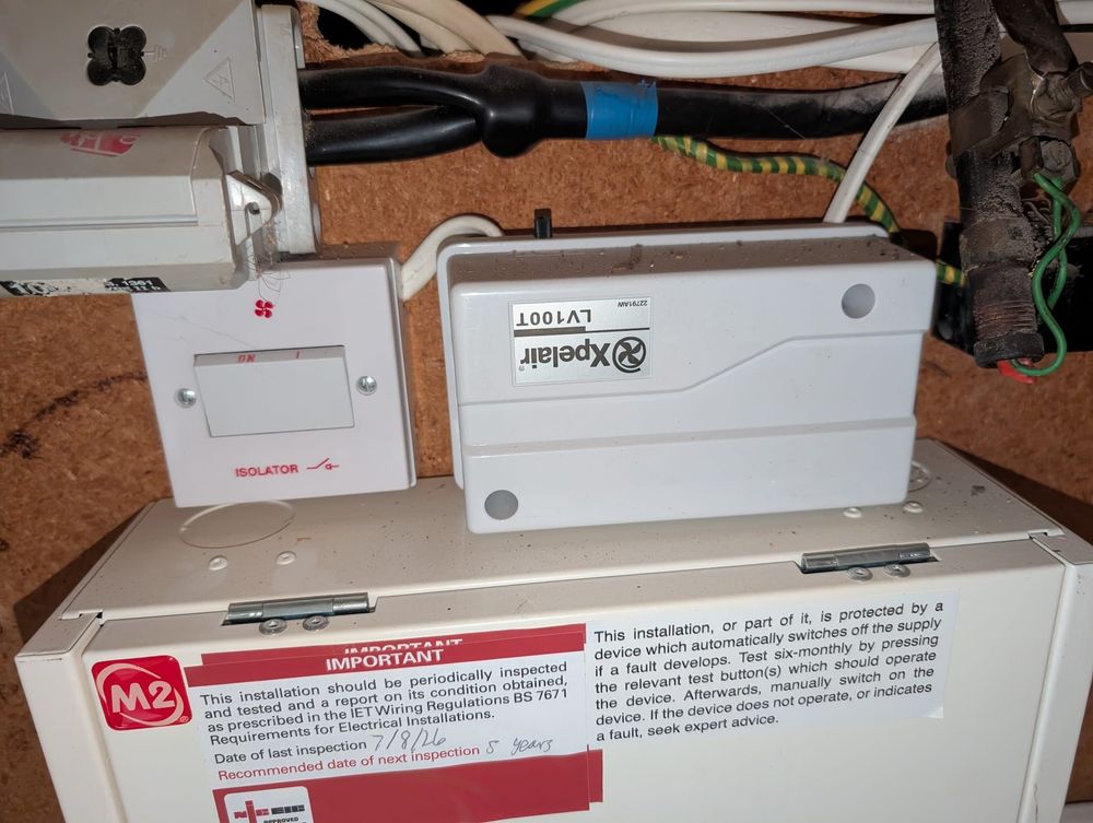
Consumer unit
Maximum Zs Values 18th Edition Table PDF: A Practical UK Electrician Reference
If you searched for a maximum Zs values 18th Edition table PDF, you probably want a quick reference you can print or keep beside the tester. The snag is that a table is only useful when it says what the figures mean, which devices it covers, and whether the comparison is based on the 100% permitted value or an adjusted cold-test value.
Download the one-page maximum Zs table PDF for printing or keeping beside your tester.
This is an original, deliberately scoped reference for common protective-device checks. It is not an official BS 7671 reproduction, and it does not replace the standard, design verification, or manufacturer information. The applicable value still depends on the protective device and the required disconnection time.
Quick summary
- Confirm the protective device, its rating, and the relevant disconnection-time basis before choosing a maximum Zs value.
- Treat the 100% figure as the permitted, operating-temperature basis.
- Treat an 80% figure as an adjusted comparison value for the relevant cooler test conditions. It is not a second maximum that applies everywhere.
- Use manufacturer-specific information wherever possible, particularly for devices outside the common reference scope.
- If the reading is high or borderline, check that you are comparing like with like before deciding what it means.
The verified lookup rows
The downloadable reference contains original formula-derived rows for common BS EN 60898 MCBs and, where the overcurrent characteristic matches, BS EN 61009 RCBOs. The 100% values use 218.5 / Ia, with Ia represented as 5 × In for Type B, 10 × In for Type C and 20 × In for Type D. The 80% column follows the IET worked-example convention of applying 0.8 to the displayed 100% value.
| Curve | Rated current | 100% maximum Zs (Ω) | 80% adjusted comparison (Ω) |
|---|---|---|---|
| Type B | 6 A | 7.28 | 5.82 |
| Type B | 10 A | 4.37 | 3.50 |
| Type B | 16 A | 2.73 | 2.18 |
| Type B | 20 A | 2.19 | 1.75 |
| Type B | 32 A | 1.37 | 1.10 |
| Type B | 40 A | 1.09 | 0.87 |
| Type B | 50 A | 0.87 | 0.70 |
| Type B | 63 A | 0.69 | 0.55 |
| Type C | 6 A | 3.64 | 2.91 |
| Type C | 10 A | 2.19 | 1.75 |
| Type C | 16 A | 1.37 | 1.10 |
| Type C | 20 A | 1.09 | 0.87 |
| Type C | 32 A | 0.68 | 0.54 |
| Type C | 40 A | 0.55 | 0.44 |
| Type C | 50 A | 0.44 | 0.35 |
| Type C | 63 A | 0.35 | 0.28 |
| Type D | 6 A | 1.82 | 1.46 |
| Type D | 10 A | 1.09 | 0.87 |
| Type D | 16 A | 0.68 | 0.54 |
| Type D | 20 A | 0.55 | 0.44 |
| Type D | 32 A | 0.34 | 0.27 |
| Type D | 40 A | 0.27 | 0.22 |
| Type D | 50 A | 0.22 | 0.18 |
| Type D | 63 A | 0.17 | 0.14 |
The 80% column is included to stop a common mix-up. It is an adjusted comparison value, not a replacement for the 100% permitted value. Every displayed row has been rechecked against the approved formula and scope. No fuse, MCCB, or manufacturer-specific row is included.
How the 32 A Type B example is calculated
The IET explanation gives the Appendix 3 calculation method as:
Zs = (U0 × Cmin) / Ia
Using 230 V and Cmin = 0.95 gives 218.5 / Ia. For a common BS EN 60898 Type B device, the worked example uses Ia = 5 × In for the relevant instantaneous operating range.
For a 32 A device:
Ia = 5 × 32 = 160 A
Zs = 218.5 / 160 = 1.365625 Ω
Rounded to two decimal places, that is 1.37 Ω at 100%. Following the IET worked-example convention, applying the 0.8 comparison to the displayed value gives 1.37 × 0.8 = 1.096 Ω, shown as 1.10 Ω.
That calculation supports the displayed example. It does not give permission to extrapolate the table to every protective device. Use the applicable source and manufacturer data for the device actually installed.
Which figure should you compare?
The two columns answer different questions.
| What you are trying to establish | Reference basis |
|---|---|
| The maximum value on the operating-temperature basis | The 100% permitted maximum Zs value |
| A comparison with a reading taken under the relevant cooler test conditions | The adjusted 80% comparison value, where that basis applies |
| The value for a device with manufacturer-specific characteristics | The current manufacturer information or applicable device data |
The reason the figures can differ is that the Chapter 41 tabulated values are based on operating-temperature conditions, while lower values in testing guidance can provide a comparison basis for readings taken under cooler conditions. Do not turn the 80% convention into an unconditional instruction.
For the underlying explanation, see the IET article Why are the values of maximum earth fault loop impedance different?.
Disconnection time still matters
Maximum Zs is not a free-floating number. It has to be compatible with the protective device and the required disconnection time for the circuit.
The IET gives common TN-system examples of 0.4 seconds for final circuits up to 63 A with a socket-outlet, and 5 seconds for distribution circuits. Those are examples, not an exhaustive disconnection-time table. Confirm the actual circuit arrangement, protection, and applicable basis before relying on a figure.
The IET's maximum earth fault loop impedance guidance explains the relationship between the device, disconnection time, manufacturer data, and the calculation method.
What this quick reference does not cover
This is not a universal protective-device table. In particular, do not assume that a common BS EN 60898 example applies to:
- MCCBs and other devices covered by BS EN 60947-2
- fuses
- unusual protective arrangements
- any device where manufacturer-specific information changes the applicable value
For these cases, use the relevant manufacturer or device data wherever available. A generic PDF cannot replace design verification.
Common mistakes
Calling the 80% value “the maximum Zs”
That loses the comparison basis. Label it as an adjusted 80% comparison value and keep it beside the 100% permitted value.
Treating one generic table as universal
Protective-device values vary between device types and manufacturers. A neat-looking PDF is not evidence that its row applies to the device in front of you.
Presenting a copied table as official
This reference must remain an original formula-derived summary with visible scope, method, and revision notes. It must not be presented as a complete or official reproduction of BS 7671 or another protected third-party table.
Recording a result without its basis
Keep the chosen reference basis alongside the measured result and circuit details. That makes it clear whether the comparison used the 100% operating-temperature value, an adjusted test comparison, or manufacturer-specific data.
What to do when the measured Zs is high
First, identify the device and confirm the required disconnection-time basis. Then check that the reference value and the test comparison are from the same basis. If the device is outside the generic scope, go to the relevant manufacturer information rather than forcing the reading into this table.
For a device-specific check, use the TestFast max Zs calculator. For the fuller explanation of the calculation and the surrounding inspection context, use the canonical maximum Zs article.
When the result is still high or borderline, record the actual reading and the reference basis clearly in the certificate or report workflow. The number needs its context.
PDF and print reference notes
Asset note for production: The generated downloadable one-page PDF carries:
- a revision date and maintenance owner
- the original calculation/source method
- the device scope beside each table section
- separate 100% permitted and adjusted-comparison columns
- a warning for MCCBs, fuses, unusual arrangements, and manufacturer-specific data
- a statement that it is not an official BS 7671 reproduction
Keep the HTML table available as well. The PDF should support quick printing, not become the only place where the figures exist. The Type B, Type C and Type D rows in this version have been rechecked; RCBO use remains conditional on matching overcurrent characteristics, and MCCB/fuse rows remain out of scope.
Further reading
- IET: Determining the maximum earth fault loop impedance for protective devices
- IET: Why are the values of maximum earth fault loop impedance different?
- Electrical Safety First: master earth fault loop table PDF — check the current document manually before relying on it for a technical or numeric claim.
Ready to transform your EICR workflow?
Join hundreds of UK electricians who are saving hours on every report with TestFast.