Maximum Permitted Zs 18th Edition: How the Number Is Decided and When It Applies
What the number means, where it comes from, the 100% / 80% / manufacturer choice

Written by
Michael Adrian
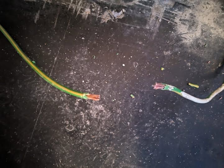
Earth bonding broken
If you've typed "maximum permitted Zs 18th edition" into a search bar, you probably weren't after a number. You were after the basis of the number — which table, which basis (design, certificate, or cold test), and whether the figure is still right as of 2026.
The 18th Edition has been with us since 2018, and Amendment 4 dropped in April 2026. The headline protection numbers — the maximum earth fault loop impedance figures electricians compare against on every certificate — come from BS 7671 Tables 41.2, 41.3 and 41.4. Amendment 4 does not change those tables. The structure is the same, the Cmin factor is the same, the disconnection-time framework is the same.
What this guide does:
- explains what "maximum permitted" actually means (it's a regulatory ceiling, not a generic chart figure)
- shows where the number comes from — the Appendix 3 formula and Cmin = 0.95
- sorts out the 100% tabulated, 80% adjusted, and manufacturer-data question (this is where most of the confusion lives)
- covers the TT / 30 mA RCD case at 1667 Ω, which most table-only sites skip
- gives a practical route when the measured reading is above the permitted figure
For the actual numbers for specific MCBs, RCBOs and fuses, see the companion Max Zs Values 18th Edition Table or punch the rating into the Max Zs calculator. This piece is the why behind those numbers.
What "maximum permitted Zs" actually means
Zs is the earth fault loop impedance at the furthest point of a circuit — the total impedance the fault current sees on its way around the loop back to the source. In simple form:
Zs = Ze + (R1 + R2)
- Ze — the external earth fault loop impedance, controlled by the DNO/DSO and measured at the origin
- R1 + R2 — the resistance of the line conductor and the circuit protective conductor (CPC) for the final circuit, measured during test
"Maximum permitted" is the regulatory/design ceiling for that figure. Under automatic disconnection of supply (ADS), the measured Zs has to be low enough that the protective device (MCB, RCBO, fuse, RCD) actually disconnects in the time BS 7671 requires. The "permitted" value is the upper bound below which the disconnection can be guaranteed, for the device and the disconnection time you've chosen.
A few things follow from that:
- The permitted value is tied to the device, not just the circuit. A 32 A Type B MCB and a 32 A Type C MCB have different permitted Zs at the same disconnection time, because they trip at different multiples of In.
- The permitted value is tied to the disconnection time. The same 32 A Type B has one permitted Zs at 0.4 s and a different one at 5 s.
- "Permitted" is the design ceiling, not a measured pass mark. On site, you compare your measured Zs to a comparison figure, and the relationship between the two is what catches people out — covered below.
Where the maximum permitted Zs number comes from
The permitted Zs values for BS EN 60898 and BS EN 61009 devices are derived using the Appendix 3 formula from BS 7671:
Zs = (U0 × Cmin) / Ia
- U0 — nominal line-to-earth voltage (230 V on TN systems)
- Cmin — a correction factor of 0.95 that accounts for voltage variations on the supply
- Ia — the current that causes operation of the protective device in the specified time, taken from manufacturer data
Worked example for a 32 A Type B MCB on a TN system at 0.4 s:
- U0 = 230 V
- Cmin = 0.95
- Ia for instantaneous trip ≈ 5 × In = 5 × 32 = 160 A
- Zs = (230 × 0.95) / 160 = 218.5 / 160 = 1.37 Ω (100% tabulated value)
- 80% adjusted comparison figure = 1.37 × 0.8 = 1.096 → 1.10 Ω
That 1.37 / 1.10 pair is the most-cited worked example in the trade for a reason — the same numbers fall out of the IET method and any compliant calculator. The cleanest accessible explanation of this formula (and why Cmin and the manufacturer-data override rule matter) is the IET Wiring Matters article from March 2023 on determining the maximum earth fault loop impedance for BS EN 60898 and BS EN 60947-2 devices.
BS 7671 publishes the resulting permitted Zs in Tables 41.2, 41.3 and 41.4 for the common MCB types, with supporting tables for fuses (BS 88, BS 1361, BS 3036) and RCBOs. Those tables are the working reference, not the Appendix 3 formula itself — but the formula is the reason the tables have the numbers they do.
A common trap: "Cmin was introduced in the 18th Edition." It wasn't. The 0.95 Cmin factor came in under the 17th Edition Amendment 3 (2015). The 18th Edition carried it forward unchanged. Worth knowing if you're cross-referencing older training material or older on-site guides — the older sources will show different (higher) figures because they pre-date Cmin.
Where this sits as of 2026 — Amendment 4 status. BS 7671 Amendment 4 was published on 15 April 2026. According to the NICEIC Amendment 4 explainer and corroborating trade coverage (ECA, EAL), the amendment does not change the fundamental protection structure, and Tables 41.2–41.4 are unchanged from the BS 7671:2018+A2:2022+A3:2024 version. The previous version is scheduled for withdrawal on 15 October 2026. Practically, this means the 1.37 Ω figure for a 32 A Type B is the same number it was last year, and the same number it will be in October. The Cmin factor and disconnection-time framework are also unchanged. If a piece of training material you've just been handed quotes a different permitted Zs for the same device, check the BS 7671 version it's citing before changing your number.
100% tabulated, 80% adjusted, and manufacturer data — which one to use
This is the part most electricians get caught on, and it's the reason this question gets asked as a search query at all.
| Basis | What it is | When to use it | Where to find it |
|---|---|---|---|
| 100% tabulated | The permitted Zs at operating temperature (e.g. 70 °C for thermoplastic), straight from BS 7671 Tables 41.2–41.4 or derived from the Appendix 3 formula | This is the figure you record on the schedule of circuit details on the certificate | BS 7671 Tables 41.2–41.4; the IET On-Site Guide; the TestFast Max Zs Values table |
| 80% adjusted | The 100% figure × 0.8 — the practical comparison figure used when your test reading is taken cold | This is the figure you compare your measured Zs against on site, because a cold reading is lower than the operating-temperature reading would be | IET Guidance Note 3; IET On-Site Guide; the TestFast calculator shows both |
| Manufacturer data | The specific Ia and permitted Zs published by the device manufacturer (e.g. for BS EN 60947-2 MCCBs) | Use this wherever it's available. Appendix 3 of BS 7671 explicitly says the tabulated values are generic and that manufacturer's data should be used when given | Device data sheet; Appendix 3 of BS 7671 |
The two common mistakes:
- Recording the 80% figure on the schedule of circuit details. The schedule should hold the 100% value. The 80% is a comparison tool for your measured reading, not the design ceiling.
- Comparing the measured cold reading against the 100% figure and concluding a fail. A cold test reading is naturally lower than the operating-temperature reading would be; the 80% rule exists precisely to give you the right comparison baseline. If you don't apply it, you'll write C2s that aren't actually C2s.
The clearest reader-facing explanation of why BS 7671's published values (operating temperature) and the On-Site Guide / GN3 values (cold, adjusted) differ is the IET Wiring Matters article from May 2024 on why the values of maximum earth fault loop impedance differ between publications. Read that if you want the Notes 2 and 3 under Tables 41.2–41.4 explained in plain English.
If in doubt, manufacturer data wins. Appendix 3 says it; the IET article repeats it; the trade convention is to default to manufacturer data wherever it exists. This is most often relevant for BS EN 60947-2 MCCBs, which have a much wider spread of let-through characteristics than BS EN 60898 MCBs. The 100% table figure is a generic ceiling; the manufacturer figure is the device-specific one.
Common disconnection times that shape the permitted Zs
The permitted Zs figure changes with the disconnection time the circuit has to meet. The same MCB has a tighter permitted Zs at 0.4 s than at 5 s, because at 0.4 s you need more fault current to clear the device fast enough.
Common TN-system examples (not an exhaustive list — check the actual circuit arrangement):
- 0.4 s — final circuits up to 63 A with a socket-outlet
- 0.4 s — final circuits up to 32 A serving fixed equipment only
- 5 s — distribution circuits
- 5 s — final circuits exceeding 32 A that do not serve a socket-outlet
Source: IET Wiring Matters issue 94, Table 1. TT systems, 110 V systems, and reduced low-voltage systems have their own disconnection-time framework — different tables, different numbers. Don't assume the TN list above covers your case.
The practical point: when you record the permitted Zs on the schedule of circuit details, make sure it matches the disconnection time the circuit actually has to meet. A 32 A radial serving fixed equipment in a TN system at 5 s has a different (looser) permitted Zs than the same MCB on a socket-outlet final at 0.4 s.
TT earthing, RCDs, and the 1667 Ω case
This is the case most public Zs tables skip, and it's the case that comes up on TT systems all the time.
On a TT system, the impedance of the installation earth electrode is usually too high to deliver enough fault current to trip an MCB. The protective device for ADS on TT is therefore usually an RCD, not an MCB. BS 7671 Table 41.5 gives the maximum permitted Zs for this arrangement: 1667 Ω for a 30 mA RCD (the standard IΔn for additional protection on most final circuits).
That number — 1667 Ω — is the upper bound below which the RCD is guaranteed to operate within the required disconnection time at its residual current rating. It's huge compared to a typical TN permitted Zs (single-digit ohms), which is exactly the point: on TT, the design isn't relying on fault-current magnitude to clear the device, it's relying on the imbalance-detection of the RCD.
Field note — Note 2 under Table 41.5. BS 7671 Table 41.5 includes a note that a Ze reading above 200 Ω "may not be stable". This is a soft signal, not a fail. The point is that very high electrode impedances can be unreliable across seasonal variation (soil moisture, frost, dry spells) and the inspector is expected to use judgement about the installation conditions. If you record a high Ze on a TT install, the context — when the reading was taken, what the conditions were, whether the electrode is in good condition — matters as much as the number. Worth flagging on the certificate. The Professional Electrician technical article on existing installations that don't comply covers this in more detail.
If you want the 1667 Ω case in the context of "what does this look like next to a 30 mA RCD", the framing is: 50 V (the IET-conventional touch voltage limit) / 0.03 A (the RCD's IΔn) = 1667 Ω. That's the calculation behind the table figure.
What to do if your measured Zs is above the permitted value
If your measured Zs is above the comparison figure (80% of the tabulated value, or the manufacturer figure), you've got three reasonable next steps, and the right one depends on context.
1. Investigate the cause. High measured Zs is a symptom, not a diagnosis. Common culprits:
- High Ze — usually a DNO-side issue. Verify with a repeat measurement at the origin; if Ze is high, the problem isn't your installation
- Long R1 + R2 — undersized CPC, long cable run, or both. A 230 V radial to a garage on a 2.5/1.5 T&E is the classic example
- Loose or high-resistance CPC connections — back-boxes, earth clamps, junction boxes, accessory terminals
2. Reduce the loop impedance. Options that don't require redesigning the whole circuit:
- Supplement the electrode (TT case) — additional rod, plate, or connection to a more effective electrode
- Increase the CPC size — particularly on long runs
- Shorten the cable run if the routing can be revised
- Add parallel earth paths if the building structure allows it
3. Upgrade the protective arrangement. Sometimes the right answer isn't to fix the loop, it's to fix the device:
- Add a 30 mA RCD for ADS in addition to the MCB (on TN, this is supplementary protection, not a substitute for the disconnection-time check)
- On TT, the RCD is already the protective device — if the loop is too high for the RCD to operate, the electrode or installation earth needs work
- Change the MCB type (e.g. Type B to Type C) — this increases Ia, which lowers the permitted Zs, so this only makes the problem worse; usually the wrong move
Inspection context — coding the result. On an EICR, a measured Zs above the comparison figure against the permitted value is typically coded C2 (potentially dangerous) where the disconnection time cannot be achieved. The word "typically" matters — coding is judgement. A reading slightly over the comparison figure on an otherwise sound installation, with no evidence of inability to disconnect, may be C3 (improvement recommended) depending on the inspector's view. Blanket "high Zs equals C2" is the wrong framing. The IET Code of Practice for EICRs and your trade body's guidance are the actual sources for coding decisions; this article can't tell you what code to put on a specific certificate.
This is also the point where the recording matters as much as the reading. If your permitted Zs basis (100% tabulated, 80% adjusted, or manufacturer) and the measured Zs are both on the certificate with the right columns, anyone reading it later — buyer, seller, next inspector, solicitor — can see exactly what was compared against what. That's what the EICR software is built for: the basis, the measurement, the comparison, the outcome, all in the right place on the certificate.
Quick reference: 32 A Type B on TN
For the most common worked example, all in one place:
| Item | Value |
|---|---|
| Device | 32 A Type B BS EN 60898 MCB |
| System | TN |
| Disconnection time | 0.4 s |
| U0 | 230 V |
| Cmin | 0.95 |
| Ia (5 × In) | 160 A |
| 100% tabulated Zs | 1.37 Ω |
| 80% adjusted (cold-test comparison) | 1.10 Ω |
| Manufacturer data override? | Use the manufacturer's figure if given; otherwise the 1.37 Ω tabulated value is the design ceiling |
If the measured Zs on site is below 1.10 Ω cold, the circuit has headroom. If it's between 1.10 and 1.37 Ω, you're above the cold-test comparison but still within the design ceiling — investigate and record context. If it's above 1.37 Ω, you've exceeded the permitted Zs and the next step is one of the three options above.
Sources and further reading
- IET Wiring Matters, Determining the maximum earth fault loop impedance for protective devices to BS EN 60898 / BS EN 60947-2 (Mar 2023) — Appendix 3 formula, Cmin = 0.95, manufacturer-data override, TN disconnection times
- IET Wiring Matters, Why are the values of maximum earth fault loop impedance different (May 2024) — operating-temperature vs cold-test explanation
- NICEIC, Understanding BS 7671:2018 + Amendment 4:2026 IET update — Amendment 4 publication date, withdrawal date, and confirmation that Tables 41.2–41.4 are unchanged
- Electrical Safety First — Master Earth Fault Loop Table (PDF) — useful printable quick-reference
- Professional Electrician, "Back to the future: what happens if an existing installation doesn't comply…" — Table 41.5 / 1667 Ω context and Note 2 framing
FAQ
What is the maximum permitted Zs for a 32 A Type B MCB on a TN system? 1.37 Ω (100% tabulated) or 1.10 Ω (80% cold-test comparison). The 1.37 Ω is the figure for the schedule of circuit details; the 1.10 Ω is the figure you compare your measured Zs against on site.
Did the 18th Edition max Zs values change in Amendment 4? No. BS 7671 Amendment 4 (published April 2026) leaves Tables 41.2–41.4 and the Cmin factor unchanged. The previous version (BS 7671:2018+A2:2022+A3:2024) is scheduled for withdrawal on 15 October 2026.
What is the maximum permitted Zs for a 30 mA RCD on a TT system? 1667 Ω, per Table 41.5 of BS 7671. Note 2 under the table flags Ze readings above 200 Ω as potentially unstable — context matters as much as the number.
Ready to transform your EICR workflow?
Join hundreds of UK electricians who are saving hours on every report with TestFast.